
Efficient lifting isn’t just about horsepower or boom length — it’s about knowing precisely what your crane can safely lift at any given angle or radius. This is especially critical for off-road machinery operators, where uneven ground and variable loads make accurate load assessment essential. In this article, we’ll walk you through everything you need to know about how to read and interpret a crane load chart, helping you make safer, smarter lifting decisions on any worksite.
What Is a Crane Load Chart?
In simple terms, a crane load chart is a technical document or graph provided by the crane manufacturer that shows how much weight the machine can safely lift under various conditions. It’s the operator’s primary safety reference.
Every load chart is built on the crane’s structural design limits, hydraulic system performance, and stability calculations. Rather than a single value, the chart presents a grid or series of curves indicating how the maximum lifting capacity changes depending on several variables — boom length, boom angle, radius, and counterweight setup.
In off-road settings — such as forestry, pipeline installation, or construction on soft ground — interpreting the chart correctly means preventing overloads, tip-overs, and hydraulic overstrain.
Key Points of a Crane Load Chart
Understanding the layout and logic of a load chart is the first step toward using it effectively. While formats may differ across manufacturers, several key parameters always appear on a crane load chart:
| Parameter | Description / Importance |
|---|---|
| Rated Lifting Capacity | The crane’s maximum allowable weight for a given boom length and radius. |
| Lifting Radius | The horizontal distance between the crane’s rotation center and the lifted load. |
| Boom Length and Angle | Define the geometry of the lift; both affect stability and capacity. |
| Counterweight & Outriggers | Determine balance and ground stability, especially critical off-road. |
| Attachment Deductions | Accessories like hooks and slings that reduce the net lifting capacity. |
Each variable interacts with the others. For instance, extending the boom reduces load capacity, while increasing the boom angle (raising it more vertically) improves it. These interdependencies form the foundation of safe crane operation.
How to Read a Load Chart on a Crane?
Here’s our step-by-step approach to interpreting crane load charts accurately — one that applies to both fixed and rough-terrain cranes used across off-road sites.
Step 1: Match the Right Configuration
Your first task is to identify the correct configuration in the manual or display interface. Most cranes feature multiple load charts based on:
- Counterweight mass (full, partial, or none)
- Outrigger deployment (fully, partially, or retracted)
- Extension setup (main boom or jib attachment)
Each configuration can vary in capacity by up to 50% or more. Using the wrong chart means guessing — a mistake operators can’t afford in the field.
Step 2: Identify Boom Condition
Next, find the crane’s actual boom length and angle.
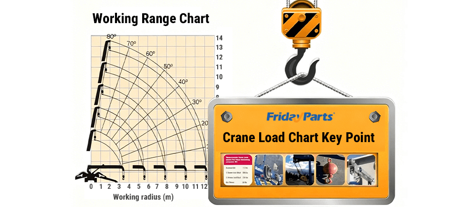
In load chart graphs, these usually appear as:
- X-axis: Lifting radius (horizontal distance)
- Y-axis: Lifting capacity (tons or kilograms)
- Curve family: Boom lengths (or extension stages)
Select the curve corresponding to your boom configuration. Then, confirm the minimum and maximum elevation angles listed. For example:
Always stay between those safe angles — below-minimum or above-extension limits can cause tipping or structural stress.
Step 3: Determine the Lifting Radius
Measure the distance from the crane’s rotation axis to the load’s hook point — not just by estimation. For off-road conditions, where footing varies, the actual radius can shift as the machine settles into soft soil.
You can measure it with:
- A laser distance meter
- Or manually, using boom length × cos(boom angle)
Example:
If the boom is 20 meters long at a 45° angle,
radius = 20 × cos(45°) ≈ 14.1 m.
Locate this radius value on the load chart’s horizontal axis, then move vertically to find the intersection with your boom’s capacity curve.
Step 4: Calculate Maximum Lifting Capacity
Once you’ve identified where the lifting radius meets the boom curve, read across to the vertical axis for the maximum total lifting weight.
Example:
- Boom length: 20 m
- Elevation angle: 60°
- Radius: 10 m
- Resulting maximum lifting capacity: 15 tons
This capacity includes all attachments — meaning you must subtract their combined weight to get the net load you can safely lift.
Step 5: Deduct Attachment and Hook Weights
Don’t forget every component suspended under the boom adds weight — hooks, slings, shackles, and spreader bars all count.
If the total attachment weight is 0.8 tons and your chart shows a 10-ton maximum, the actual permissible load is:
10 − 0.8 = 9.2 tons
Skipping this deduction is one of the most common reasons for overload incidents on off-road cranes.
Step 6: Verify Ground Support and Stability
Finally, interpret the chart based on the actual terrain.
Remember: most load charts are derived under lab-level flat-ground conditions. On uneven or soft ground — typical in off-road applications — the effective capacity can drop by 10–20%. Always factor in ground compaction, outrigger pads, and slope before finalizing a lift plan.
In addition to understanding the load chart itself, maintaining critical crane parts such as hydraulic cylinders, wire ropes, load sensors, and outrigger components is equally important. Worn or poorly maintained parts can distort real lifting capacity, making even a correctly interpreted load chart unreliable in demanding off-road conditions.
Common Mistakes to Avoid
Even experienced operators make critical errors when reading crane load charts. Here are some of the most frequent — and how to prevent them.
1. Using the Wrong Configuration Chart
Always confirm counterweight, boom, and outrigger positions match exactly. A mismatch between “full counterweight” and “no counterweight” data can halve the safe limit.
2. Ignoring Attachment Weights
Track and log every lifting accessory used regularly. Subtract their combined mass before calculating.
3. Relying on Estimated Radius
Visual guesses don’t work for precision operations. Use measurement tools or basic trigonometric calculations.
4. Operating Beyond Extension Limits
Never extend beyond the manufacturer’s specified maximum boom length or below the minimum boom angle listed on the chart.
5. Neglecting Terrain Conditions
For off-road lifting, always assess slope angles and soil firmness. Even a 3° incline can reduce lift stability significantly.
FAQs
Q1: What is the purpose of the bold line on a crane load chart?
It defines the safe operating boundary, usually representing full counterweight and fully extended outriggers. Anything beyond it is prohibited.
Q2: How do I calculate crane capacity from the load chart?
- Match configuration (boom, outriggers, counterweight).
- Measure lifting radius.
- Locate the boom curve to find the maximum capacity.
- Subtract attachment weight.
Q3: What does a 100-ton crane mean?
It’s the maximum rated lifting capacity achievable under ideal conditions: full counterweight, minimal radius, and maximum boom angle. Real working capacity will almost always be lower.
Q4: Why do off-road surface differences matter so much?
Because uneven or soft ground shifts the machine’s center of gravity and reduces effective support, decreasing the real-world lifting capacity compared to chart conditions.
Conclusion
Reading a crane load chart is more than following numbers — it’s about interpreting the physics of lifting safely, especially in unpredictable off-road environments. By understanding how each parameter interacts and maintaining equipment with quality parts, operators can ensure stable, efficient, and hazard-free performance across every project.