

This guide provides the 3-wire alternator wiring diagram based on the industry-standard. The Delco 10SI alternator is used here as a representative 3-wire charging system. Wiring configurations may vary across modern heavy-duty equipment with ECU-controlled charging systems. We provide the technical logic and precise wiring specifications required to ensure your diesel engine’s electrical system is safe and efficient.
Identifying the Components of a 3-Wire System
To successfully wire a modern internal regulator alternator, we must identify four primary components and the specific roles of the terminals on the Delco 10SI-style unit:
- Alternator: An internally regulated unit that manages voltage and current without the need for an external mechanical regulator.
- Battery: The 12-volt power storage for the tractor.
- Ignition Switch: The keyed switch that provides “excite” power only when the machine is in the “ON” or “ACC” position.
- Indicator Light or Diode: A 12-volt incandescent bulb or a diode placed in the exciter circuit to prevent electrical feedback from the alternator to the ignition coil.
Terminal Roles
- BATT Terminal: The heavy threaded stud on the rear of the case; the main power output.
- Terminal 1 (Excite): The left-hand terminal (when looking at the rear plug); used to “turn on” the charging field.
- Terminal 2 (Sense): The right-hand terminal; used by the regulator to monitor system voltage.
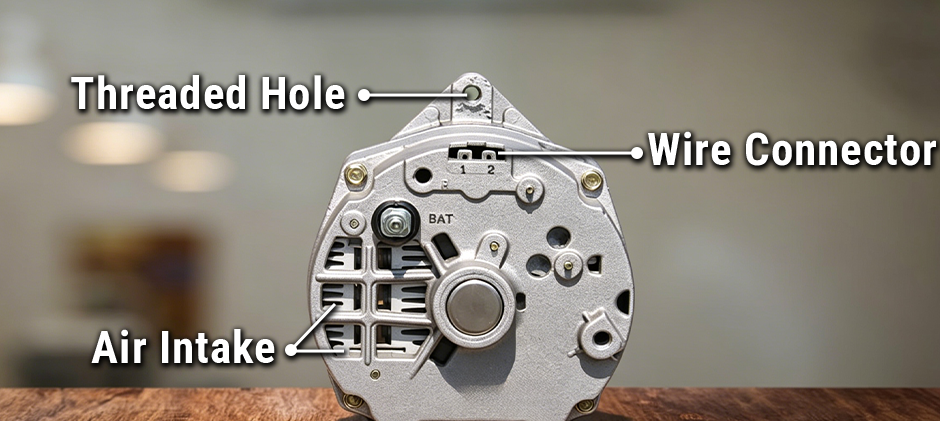
We must ensure the sense wire accurately reads the system voltage to prevent the regulator from overcharging the battery.
The Primary 3 Wire Alternator Wiring Diagram Breakdown 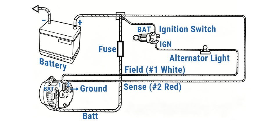
Main Charging Output Wire
Run a thick wire straight from the alternator’s BATT bolt to your starter solenoid or main battery positive connection.
- #8 gauge wire is the best pick: it cuts down voltage loss and gives you an extra safety buffer, especially for high-amp alternators or long wiring runs.
- #10 gauge works as the absolute minimum, but step up to #8 whenever you can.
- Add a 50A maxi-fuse or matching fusible link (like #12 gauge) inline on this wire. If this thick power wire rubs through and shorts to the engine block, this fuse stops a fire from breaking out.
Exciter Wire (Terminal 1)
Grab a #16 gauge wire and run it from the IGN/ACC pin on your ignition switch to your dashboard.
Install either a 12V dash charge light bulb or a diode at this dash point, then extend the same #16 gauge wire from the bulb or diode to Terminal 1 on the alternator plug.
The dash light has two jobs: it shows you if your charging system works, and it works as a resistor to avoid engine run-on. Engine run-on happens when the alternator still feeds power to the ignition coil after you turn off the key.
If you don’t want a dash warning light, just use a diode here to block reverse current instead.
Sense Wire (Terminal 2)
Many mechanics cut corners by jumping Terminal 2 directly to the alternator’s BATT bolt.
This quick fix works for basic setups, but it’s not ideal for rigs with heavy electrical loads such as large work lights. The proper install routes Terminal 2 all the way back to your main power junction block or starter solenoid.
This setup lets the alternator’s voltage regulator make up for power loss on the main charging wire. That way, your battery always receives a stable, accurate 14.2V charging voltage.
Step-by-Step Installation for Diesel Machine
- Mechanical Grounding: Mount the Delco 10SI alternator onto its bracket and tighten the mounting bolts. Make sure the alternator housing has clean, bare metal contact with the engine. A poor ground can cause charging problems and may shorten the life of the voltage regulator.
- Connect the Main Output Wire: Run an #8 gauge wire from the alternator’s BATT terminal to the starter solenoid or the battery positive terminal. Install a properly sized fuse or fusible link in this wire to protect the charging circuit.
- Connect the Sense Wire: Connect Terminal 2 to the main power junction or the starter solenoid. This lets the regulator read the system voltage more accurately and helps keep the battery charging properly.
- Connect the Exciter Wire: Use #16 gauge wire for Terminal 1. Run the wire through a charge warning light or an inline diode, then connect it to a keyed IGN or ACC power source.
Quick Tip: After starting the engine, the alternator may not begin charging right away if it’s idling too low. Give the engine a quick rev until the alternator starts charging. Once it does, the charge warning light should turn off, and the alternator will continue charging even after the engine returns to idle.
Troubleshooting Common Wiring Errors
Parasitic Battery Drain
If your battery dies after sitting a few days, check your Terminal 1 wiring. Terminal 1 must connect to keyed ignition power that only turns on with the key.
If you wire Terminal 1 to constant hot battery power, the alternator’s internal field stays energized 24/7. It slowly drains your battery while the machine is off.
High Voltage Output (16V–18V)
If your voltmeter reads 16 volts or higher while running, the Terminal 2 sense wire is almost always the problem.
Terminal 2 tells the alternator what system voltage it’s reading. If this wire is broken, loose, or has no connection, the regulator reads 0V. Thinking the battery is dead, the alternator maxes out its output voltage. This overcharges the battery badly and will boil your battery fluid over time.
Final Thoughts
Following the correct 3-wire alternator wiring diagram is the best way to keep your charging system reliable. Good wiring, clean connections, and quality replacement parts all help reduce electrical problems and equipment downtime. At FridayParts, you’ll find a wide selection of high-quality aftermarket alternators, regulators, wiring harnesses, and other electrical parts.
