

When you’re on the road and an electrical component in your Freightliner Cascadia suddenly fails—be it the radio, a headlight, or the power window—your first instinct is to check the fuse box. But you’re not just dealing with a simple panel of fuses. The Cascadia’s advanced electrical system can be intimidating. This guide is about the Freightliner Cascadia fuse box diagram, explains the critical SAM modules, and shows you how to troubleshoot electrical issues.
Why Is the Cascadia Electrical System Different?
Older trucks have basic fuse panels, but newer rigs like the Freightliner Cascadia run on an advanced system controlled by SAM modules — Signal Detect and Actuation Modules. These act as the truck’s electrical brain. They take signals from switches and sensors, then control almost every feature on the truck. You mainly need to learn about two key modules:
- SAM Cab: It’s mounted inside the cab, usually behind the glove box. It handles all electrical parts inside the truck. This covers dome lights, dash gauges, radio, power windows, climate control and sleeper cabin switches.
- SAM Chassis: You’ll find it on the engine side of the firewall. It takes charge of exterior lights and core driving systems. That means headlights, taillights, turn signals, engine and transmission communication, plus the ABS brake system.
These are smart modules. They don’t just send power through fuses. When you flip the headlight switch, the module gets that signal first, then decides to power up the headlights. This extra complexity means electrical faults aren’t always just a blown fuse. The trouble could come from a faulty input signal, a poor ground connection, or even damage inside the SAM module.
The SAM Wall Chart
Working on this complicated system? You’ll need a reference guide. That guide is the Freightliner Cascadia fuse box diagram, officially called the SAM Wall Chart. This is your go-to resource to locate fuses, relays, circuits and connectors on the truck. No more yanking out fuses blindly — it lets you troubleshoot step by step with a clear plan.
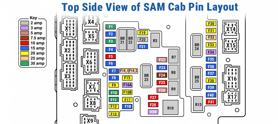
How to Read the Freightliner Cascadia Fuse Box Diagram?
Let’s break down how to read the SAM Wall Chart. We’ll use the common layout for EPA 2010 and newer Cascadias as our example.
Step 1: Identify the Main Sections
The chart is divided into two main parts: the SAM CAB and the SAM CHASSIS. Each section contains a visual layout of the fuse and relay locations, along with detailed lists that explain what each pin on every connector does.
Step 2: Find the Fuse’s Function in the Legend
Next, you need to know what each of those fuses actually controls. This is where the fuse legend comes in. Below is the comprehensive list for the SAM Cab, compiled from your images.
SAM Cab Fuse List
| FUSE | RATING | DESCRIPTION |
|---|---|---|
| F1 | 30A | PWR FD SPARE 1 & 3, BAT |
| F2 | 15A | CAB/SLPR HVAC CTRL/SHF PNL |
| F3 | 30A | PWR FD SPARE 2 & 4, BAT |
| F4 | 15A | MSF, BAT |
| F5 | 10A | OBD J1939, BAT |
| F6 | 15A | DASH PWR RCPT 1, BAT |
| F7 | 15A | DASH PWR RCPT 2, BAT |
| F8 | 15A | PHONE/RADIO, BAT |
| F9 | 20A | AMPLIFIER PWR, ACC |
| F10 | 30A | CAB HVAC MTR, BAT |
| F11 | 30A | SLPR HVAC MTR, BAT |
| F12 | 20A | DR CTRL L, BAT |
| F13 | 20A | DR LOCK/SM CRUISE |
| F14_1 | 25A | CB RADIO/FLEET MANAGEMENT SYSTEM, LVD |
| F14_2 | 25A | CB RADIO/FLEET MANAGEMENT SYSTEM, BAT |
| F15 | 20A | SLPR PWR RCPT 3, BAT |
| F16A | 3A | AUX CAB HEATER ENABLE |
| F16B | 20A | AUX COOLANT HEATER, BAT |
| F17 | 20A | SLPR PWR RCPT 4, BAT |
| F18 | 15A | TELEMATICS/WARNING SYS, BAT |
| F19 | 20A | HEATED SEAT, IGN |
| F20 | 2A | CGW, BAT |
| F21 | 15A | AREA LIGHT, BAT |
| F22 | 5A | ICU/HORN SW, BAT |
| F23 | 15A | DR INFO/GAUGE PWR, TELEMATICS, IGN |
| F24 | 7.5A | ICU/DIAG CONN, IGN |
| F25 | 10A | DASH SPLICE PACK, IGN |
| F26 | 5A | SRS-AIRBAG, IGN |
| F27 | 10A | MIRROR HEAT L |
| F28 | 10A | MIRROR HEAT R |
| F29 | 3A | SAM RELAY COILS, BAT |
| F30 | 20A | PWR RCPT 6/FRIG, BAT |
| F31 | 20A | SLPR PWR RCPT 5, BAT |
| F32 | 25A | PWR FD SPARE 5 & 6, BAT |
| F33 | 20A | SPOT LIGHT, BAT |
| F34 | 3A | BAGGAGE COMP LAMP, BAT |
| F35 | 15A | DOMELAMP CAB |
| F36 | 15A | AUX CIR FAN/RD LAMP |
| F37 | 15A | CLK/DRV INFO/CD/SLPR CLCK/KEYLESS |
| F38 | 20A | DR CTRL R, BAT |
| F39 | 15A | PWR WINDOWS R, ACC |
| F40 | 15A | PWR WINDOWS L, ACC |
| F41 | 10A | AUX HOOD MIR HEAT |
Step 3: Understanding the Relays
Beyond fuses, the system uses relays, which are electrical switches that control power to one or more circuits. The table below shows which relay distributes power to which fuses. This is a critical diagnostic step: if several fuses that are all powered by the same relay have no power, the problem is likely the relay itself, not the individual fuses.
SAM Cab Relay List
| RELAY | TYPE | POWER DISTRIBUTED THRU FUSE |
|---|---|---|
| BR21 | BISTABLE | F1, F6 |
| BR22 | BISTABLE | F3, F15 |
| BR23 | BISTABLE | F7, F14, F16A |
| BR24 | BISTABLE | F21, F30, F34, F35 |
| BR25 | BISTABLE | F17, F31, F36 |
| R3 | MICRO | F19 |
| R7 | MICRO | F23 |
| R8 | MICRO | F24, F25, F26 |
| R9 | MICRO | F9 |
| R10 | MINI | F27, F28, F41 |
| R15 | MICRO | F39, F40 |
Step 4: Put It All Together
Now, let’s use this complete information. Imagine your heated mirrors are not working.
- Consult the Fuse Legend: Scan the fuse table for “MIRROR HEAT”. You’ll find F27 (Left) and F28 (Right).
- Check the Relay Table: Notice that both F27 and F28, along with F41 (AUX HOOD MIR HEAT), are controlled by the R10 relay.
- Form a Diagnostic Plan:
- First, check fuses F27 and F28.
- If both fuses are good but have no power, the problem is unlikely to be two separate wiring issues. It’s much more likely that the R10 relay that powers them has failed.
- You can now locate the R10 relay on the SAM Cab physical diagram and test or swap it.
This multi-step process—using the fuse list, then the relay list, then the physical diagram—is the core of effective electrical troubleshooting in a Cascadia.
Common Cascadia Electrical Problems and How the Diagram Helps
Once you know how to read this diagram, you can fix those annoying common electrical problems.
Parasitic Battery Drain
Parasitic drain means electricity slowly leaks somewhere when your truck is turned off, draining the battery. Once you use a multimeter to verify the drain, the fuse box diagram becomes your most useful tool. Pull each fuse one by one while watching the multimeter reading, and you’ll find which circuit is causing the leak. Say you remove fuse F17 (Radio, BAT) and the drain stops. The diagram tells you the fault is on the radio circuit.
Lights Stop Working or Act Crazy
Lots of drivers run into odd problems: marker lights flickering or taillights not turning on. As people talk about on truck forums, this usually isn’t just a blown fuse. More often, the SAM Chassis unit or its connections are at fault. Use the diagram to find the exact circuit for the faulty lights — for example, X55/3 for trailer taillights. Then check for proper voltage at the matching SAM Chassis pins.
Don’t Skip Ground Connection Checks
SAM modules are really sensitive to bad ground connections. Corroded or loose grounds can trigger all kinds of weird electrical faults that seem unrelated. A faulty ground wire on the SAM Chassis creates way more trouble than several blown fuses.
The diagram marks every ground pin, usually labeled GND. For example, the chart lists X18/7 as the ground for the left headlight and corner turn signal. If that light malfunctions, run a voltage drop test on this ground pin first to make sure it’s solid, before buying costly replacement parts.
A Final Word
Freightliner Cascadia electrical systems can seem complicated, but the fuse box diagram (also called the SAM layout) makes troubleshooting much easier. Once you’ve found the bad relay, sensor, or other faulty part, FridayParts has reliable aftermarket replacements at a price that makes sense.
