
When timing-related faults appear in off-road machinery, the time delay relay is often blamed too soon or missed until other parts have already been replaced. Many delay problems are first misdiagnosed as sensor faults, wiring faults, or ECU issues. This guide helps identify the real fault path faster. It covers the key symptoms, what to rule out first, how to test the relay, and when replacement is the correct repair.
What Is a Time Delay Relay?
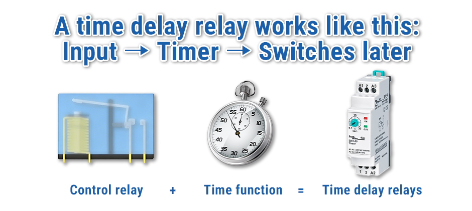
A time delay relay is a relay that switches after a preset delay instead of switching immediately. In off-road machinery, its job is to control when a circuit turns on, turns off, or stays active for a set time.
Symptoms of a Faulty Time Delay Relay
A relay fault should first be identified by what the machine is doing, not by replacing parts. Symptoms show the problem. Testing confirms the cause.
No Delay or Instant Switching
The circuit responds immediately, even though a delay should be present. A cooling fan may start too early, a warning output may trigger right away, or a timed shutdown-related function may happen too soon.
This symptom may suggest:
- The timing function inside the relay
- Wrong relay type
- Incorrect or bypassed wiring
No Response at All
The relay does not click, switch, or activate the output. In off-road machinery, that may look like:
- No delayed alarm
- No timed solenoid action
- No fan run-on after shutdown
This symptom alone does not prove relay failure. Missing input power or a bad trigger signal can cause the same result.
Incorrect Timing
The relay still works, but the delay is too short, too long, or inconsistent. This is one of the clearest signs of a timing fault because the circuit responds, but not when it should.
Intermittent Operation
The problem appears only sometimes. The machine may work normally when cold and fail after warming up, or the fault may show up only during vibration or heavy operation.
Intermittent timing faults are often misread as sensor or wiring faults first, especially on machines that work in dust, heat, and vibration.
Sequence Failure in Machine Systems
One electrical action happens out of order. One output may switch too late, another may stay on too long, or a timed step may fail. In many cases, this first looks like a control problem, but the time delay relay may still be involved.
Before Testing: Rule Out External Issues
Before removing the relay or ordering a replacement, check the rest of the circuit. A healthy relay can still appear faulty if outside conditions are wrong.
Power Supply or Fuse Problems
Check whether the relay is receiving proper voltage. A blown fuse, weak battery feed, or unstable power source can affect timing or stop operation completely.
If the machine shows power distribution issues, inspect related parts such as the fuse box and nearby circuit feeds. In some cases, the relay is not the real problem.
Bad Ground or Corroded Connection
A poor ground can cause weak switching, delayed action, or no operation at all. Corroded terminals can also create voltage drop and intermittent faults.
Check for:
- loose terminals
- burned connector cavities
- corrosion on pins
- signs of overheating
If the connection point is damaged, replacing the wiring harness connector may correct the problem without changing the relay.
Faulty Switch, Sensor, or Control Signal
The relay may be waiting for a trigger signal that never arrives. A failed switch, damaged sensor, or missing control output can stop the delay cycle before it begins.
This is a common source of wrong diagnosis in off-road equipment, especially when the fault appears only under one machine condition.
Load-Side Fault
The relay may switch correctly while the output component fails. A bad motor, failed alarm, or sticking solenoid valve can make it seem like the relay is not working.
That is why output-side confirmation matters before replacing any control component.
How to Test a Time Delay Relay?
A proper relay test should confirm three things:
- correct input
- correct delay
- correct output
Visual Inspection
Inspect the relay and socket first. Check for:
- burned smell
- cracked housing
- melted plastic
- darkened terminals
- loose pins
Visible damage is not the only sign of failure, but it is an important early clue.
Basic Multimeter Test
Use a multimeter to verify:
- Input voltage at the relay
- ground continuity
- trigger signal presence
- output voltage or contact continuity after activation
If correct voltage and trigger are present but the relay does not energize, internal failure becomes more likely.
Timing Verification Test
Measure the actual delay and compare it with the expected delay. Repeat the test more than once to check consistency.
| Test item | Column 2 | Likely diagnosis |
|---|---|---|
| Input voltage | The correct voltage reaches the relay | Low voltage or feed problem |
| Trigger signal | Command arrives at the right time | Missing trigger points upstream |
| Delay time | Actual delay matches expected delay | Wrong timing suggests a relay or a setting fault |
| Output switching | Contacts change state after a delay | No switching suggests an internal relay fault |
| Load response | Connected device operates correctly | The load-side fault may still exist |
Compare Relay Action with the Circuit Type
Confirm that the relay matches the machine circuit. On-delay, off-delay, and interval relays do not work the same way. A relay that is electrically functional but wrong for the application can still create timing faults.
Step-by-Step Time Delay Relay Troubleshooting Flow
A structured path makes relay diagnosis faster and helps avoid replacing good parts.
Step 1: Confirm Battery Voltage and Fuse Condition
Low voltage can distort relay timing or stop it from operating. Check circuit protection first.
Step 2: Verify Power and Ground at the Relay
If power or ground is weak or missing, repair that issue before moving further.
Step 3: Check the Trigger Signal
Confirm that the control signal reaches the relay when the required machine condition is met.
Step 4: Confirm Relay Energizing
Listen for relay action if possible, or measure the coil circuit directly.
Step 5: Measure the Actual Delay
Compare the measured delay with the timing required by the machine circuit.
Step 6: Test the Output Contacts
Make sure the switched side changes state after the timing period.
Step 7: Verify the Load Response
If output leaves the relay but the function still fails, inspect the controlled component.
Swap Test: A Practical Way to Confirm Relay Failure
A swap test is one of the most useful checks in real repair work. Install a known-good relay with the same type, voltage rating, pin layout, and timing range, then compare machine behavior.
A swap test is especially useful when:
- The fault is intermittent
- Heat or vibration affects the problem
- The bench test results are unclear
- The relay seems to work only sometimes
If the symptom disappears with a known-good relay and returns with the original one, relay failure becomes much more likely.
A swap test should support the diagnosis, not replace basic checks for power, ground, trigger, and load.
Time Delay Relay Maintenance Tips
Good maintenance cannot prevent every relay failure, but it can reduce unnecessary faults and help the circuit stay reliable in harsh working conditions.
Keep Connections Clean and Tight
Loose or corroded terminals can create resistance, voltage drop, and unstable relay operation. During regular inspection, check the relay socket and connector for dirt, oxidation, and heat damage.
Protect the Relay from Moisture and Contamination
Mud, water, oil, and dust can shorten relay life, especially in off-road equipment. If the relay is mounted in an exposed area, inspect the sealing condition and the surrounding protection parts.
Check for Heat Stress
High temperature around the relay or connector can damage the housing, weaken contact performance, and affect timing accuracy. Look for discoloration, melted plastic, or signs of overload near the mounting point.
Inspect the Circuit During Routine Electrical Service
When checking the machine’s electrical system, include the relay circuit in the inspection. Verify stable power supply, proper ground condition, and secure terminal contact before symptoms appear.
Replace the Relay with the Correct Type
Using the wrong relay can create repeat timing faults even if the new part is electrically functional. Always match the delay type, voltage rating, terminal layout, and timing range to the original application.
When to Replace a Time Delay Relay?
Replace the relay when testing confirms:
- Correct power and trigger signal are present, but no output occurs
- Actual delay remains outside the specification
- Output contacts do not switch correctly
- The housing or terminals show heat damage
- A known-good replacement corrects the problem
When selecting a replacement, match:
- Relay type
- Voltage rating
- Terminal layout
- Timing range
- Duty requirement
FAQ
How can it be confirmed that the relay is bad and not the sensor?
Check whether the trigger signal reaches the relay. If it does not, the fault is usually upstream rather than inside the relay.
Can a time delay relay fail intermittently?
Yes. Intermittent failure can happen when the relay has internal wear or when the circuit is affected by poor connections.
Can low voltage affect relay timing?
Yes. Low or unstable voltage can cause slow response, wrong delay, or complete failure to switch.
Conclusion
A correct time delay relay troubleshooting process starts with the symptom, rules out outside circuit problems, and then confirms relay input, timing, output, and load response in order. Following a structured troubleshooting sequence helps isolate relay failure faster and prevents unnecessary component replacement. If replacement parts are needed, FridayParts can be a practical source for aftermarket heavy equipment parts with broad compatibility, dependable quality, and competitive pricing.