

Electrical issues can bring your John Deere equipment to a sudden halt. Knowing the John Deere fuse box diagram is essential for quick diagnostics and repairs. In this guide, we’ll walk you through everything about the John Deere fuse box, from the locations, the diagrams and how you can troubleshoot problems with it.
What Are Fuses on John Deere Electrical System?
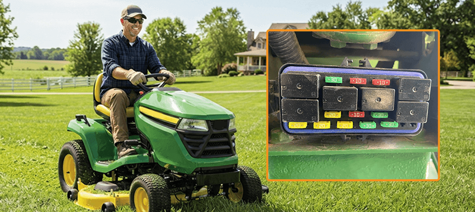
Fuses are crucial components in the electrical system of your Deere equipment. It contributes to protecting sensitive components from damage due to overcurrent. Once you get a blown fuse, it’s a sign of an electrical problem and of the need for a replacement. Ignoring recurrent blown fuses without addressing the underlying issues can lead to more costly repairs. Shop for quality amp fuses here.
John Deere Fuse Box Locations by Models
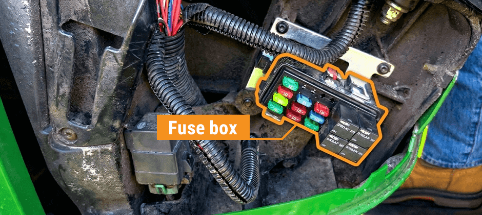
Here’s a look at fuse box locations for some popular John Deere models. Always consult your operator’s manual for the most accurate information for your Deere equipment.
| Models | Locations |
|---|---|
| John Deere 6110 Tractor | On the right-hand side console, possibly behind a small access panel |
| John Deere 5075E Tractor | Under the dashboard, on the right-hand side |
| John Deere 4440 Tractor | Inside the cab on the right-hand side console |
| John Deere 4050 Tractor | Inside the tractor cab on the right-hand side console |
| John Deere 4020 Tractor | Under the hood, on the left-hand side when facing the tractor |
| John Deere 4010 Tractor | Under the hood, typically on the left side or firewall |
| John Deere 3020 Tractor | Under the hood, often on the left-hand side or on the firewall |
Understanding the John Deere Fuse Box Diagram
Knowing the fuse box diagram is essential to troubleshooting the electrical systems of your Deere equipment. The diagram shows the location of each fuse and what circuit it protects. You can usually find the diagram on the inside of the fuse box cover or in your operator’s manual. Let’s start!
- Fuse Number: Each fuse is assigned a number
- Circuit Description: The diagram will tell you what the fuse protects, such as turn signals, fuel pump, starter solenoid and headlights.
- Fuse Amp Rating: This refers to the maximum current the fuse can handle before blowing. It can damage the circuit if you replace the blown fuse with a new fuse of higher amp rating.
- Symbols: Some diagrams use symbols to represent different circuits. Always refer to your owner’s manual for a legend.
Say your diagram shows: Fuse #5– Headlights – 15Amp
That means fuse number 5 protects the headlight circuit and should be a 15-amp fuse. If your headlights failed, check fuse #5 first.
Example Fuse Box Diagram (6120 to 6420 and 6120L to 6520L Tractor)
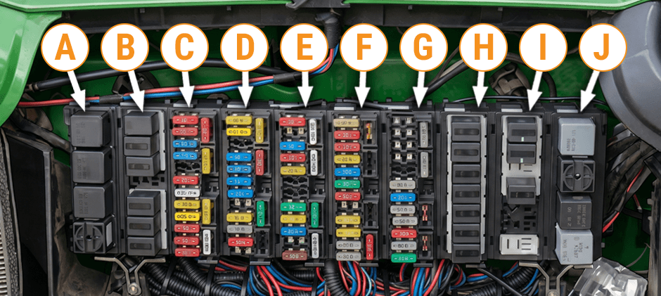
| A—Relay box K01 | B—Relay box K02 | C—Fuse box F03 | D—Fuse box F04 | E—Fuse box F05 |
|---|---|---|---|---|
| F—Fuse box F06 | G—Fuse box F07 | H—Relay box K08 | I—Relay box K09 | J—Relay box K10 |
*Sourced from manual.deere.com. See full diagram for Fuse and Relay Boxes on Tractors with Operator’s Cab and AutoPowr.
John Deere Fuse & Relay Size and Function
Here is an example of John Deere fuse and relay size and function diagram.
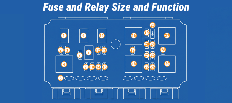
| 1-Warning Light Power Relay | 2-Fuse F1, 20-Amp: Ignition Switch | 3-Fuse F2, 30-Amp: Warning Light Power Relay, Left Turn Relay and Right Turn Relay |
|---|---|---|
| 4-Turn/Warn Relay | 5-Spare Fuse Holders | 6-Left Turn/Warn Relay |
| 7-Fuse F5, 15-Amp: Low Beam Headlights and Loader Lights | 8-Flash Logic Relay | 9-Fuse F6, 30-Amp: Junction Block, CNVC Outlet, Cigar Lighter and Fuel Transfer pump10-Fuse F7, |
| 10-Amp: Horn | 11-Right Turn/Warn Relay | 12-Fuse F3, 5-Amp: Dome Light and Radio |
| 13-Fuse F4, 20-Amp: Light Switch | 14-Fuse F8, 5-Amp: Instrument Cluster | 15-Fuse F9, 5-Amp: Instrument Cluster Diagnostics (Used only to enable diagnostic mode. Socket must be empty for normal operation.) |
| 16-Trailer Power Relay | 17-Fuse F13, 30-Amp: Rear Work Lights | 18-Rear Work Light Relay |
| 19-Fuse F10, 30-Amp: Trailer Power Relay | 20-Fuse F11, 30-Amp: Junction Block, CNVC Outlet, Air Seat, Back-Up Alarm and Mid-Mount SCV Option | 21-Fuse F15, 10-Amp: Taillights |
| 22-Fuse F17, 10-Amp: MFWD Option | 23-V2 Accessory Relay Circuit Diode | 24-Fuse F12, 10-Amp: Radio |
| 25-Fuse F16, 15-Amp: High Beam Headlights and Loader Lights | 26-Fuse F18, 10-Amp: Fuel Shut Off Solenoid, HVAC Relay, Elx Relay, Seat Switch, and Wheel Speed Sensor | 27-Accessory Relay |
| 28-Fuse F14, 30-Amp: Front Work Lights | 29-Front Work Lights Relay | / |
A/C and Wiper Fuse/Relay Block (Cab)
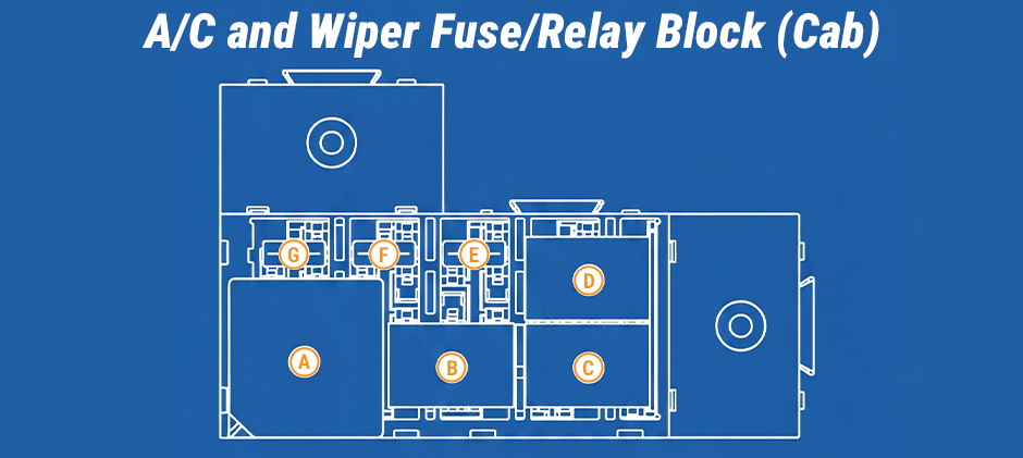
| A-HVAC Relay | B-Right Blower Relay | C-Left Blower Relay | D-Wiper System Relay |
|---|---|---|---|
| E-Fuse F24, 20-Amp: Front Wiper | F-Fuse F25, 20-Amp: Left Blower | G-Fuse F23, 30-Amp: HVAC and Right Blower | / |
PowrReverser Transmission Fuse Block
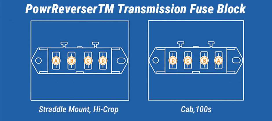
| A-Fuse F19, 10-Amp: EH Controller and Service Advisor |
|---|
| B-Fuse F20, 10-Amp: MFWD Switch, Brake Pedal Switch, Neutral Relay, Countershaft Speed Sensor, Rear PTO Switch, High/Low Shifter Switch, and EH Controller |
| C-Fuse F21, 10-Amp: EH Controller |
| D-Fuse F22, 5-Amp: EH Controller Diagnostics |
Step-by-Step Guide on Troubleshooting Electrical Problems
Once you’ve run into electrical issues on your Deere equipment, follow the steps:
- Identify the problem: What electrical component might be failing?
- Consult the fuse box diagram: Locate the fuse that protects the circuit for that component
- Inspect the fuse: Visually check the fuse for a broken filament inside the glass or a blackened appearance
- Test the fuse (Optional): Use a multimeter to test the fuse for continuity
- Replace the fuse: Replace the blown fuse with a new fuse of the same amp rating
- Test the component: See if the electrical component now works
If the new fuse blows shortly after the replacement, it seems there is a short circuit or other problem in the circuit. Stop replacing the fuse again and again. Just turn to a pro for troubleshooting and repair.
Common Electrical Issues & Related Parts
Here are common electrical issues, related parts and testing guides for your reference.
| Items | What to Do | Related Parts | Guides |
|---|---|---|---|
| Starting Problems | Check the starter fuse and the starter | Starter motor | How to Test A Starter Motor? |
| Charging Problems | Check the alternator fuse and the alternator itself | Alternator | How to Test If Alternator Is Bad? |
| Lighting Problems | Check the headlight, taillight, and turn signal fuses | Lights | / |
| Fuel Delivery Problems | Check the fuse that protects the electric fuel pump circuit | Electric Fuel Pump | / |
Wrapping up
Knowing the fuse box diagram is crucial for troubleshooting and repairing the electrical systems of your John Deere equipment. You can find the diagram in the operator’s manual and some common locations. Remember not to replace the fuse over and over again until you find the underlying problem. At FridayParts, you can learn a lot of knowledge about your John Deere electrical system and source a vast selection of quality electrical system parts. Ready to do your troubleshooting now?
