Briggs & Stratton Valve Clearance Chart: Specs and Adjustment Guide
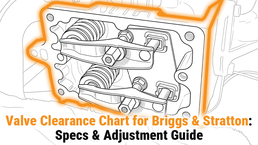
Briggs & Stratton valve clearance chart: specs and adjustment guide. A Briggs & Stratton valve clearance chart only works if the engine family is matched correctly first. Some series use L-head layouts. Others use OHV designs. Several have different values for horizontal and vertical shaft versions. L-head aluminum singles often use 0.005 to 0.007 intake. L-head cast iron singles use 0.007 to 0.009 intake and 0.017 to 0.019 exhaust. OHV singles often use 0.004 to 0.006. OHV twins commonly use 0.004 to 0.006. The adjustment procedure starts with a cold engine. Remove the spark plug, find the compression stroke, and set the piston about 1/4 inch past TDC. Measure with a feeler gauge. Adjust slowly. Tighten and recheck. Tight valves cause hard hot starting and power loss. Loose valves cause tapping noise and rough running.